

Search results for "electronics"
500 items found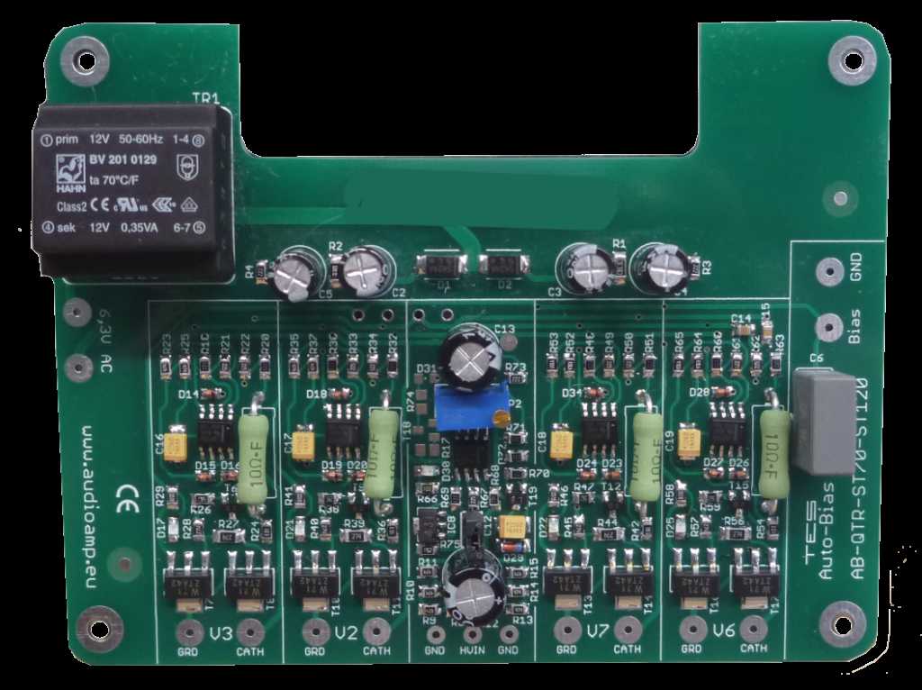
Miller Audio LLC
Miller Audio LLC <br>Dallas-Fort Worth Metropolitan Area, TX, USA <br>4255 Peppermill Lane Dallas, TX 75287 <br>972-693-5116 <br>[email protected] <br>Miller Audio LLC, based in Dallas, TX, is a privately held, audio electronics design business. We manufacture specialized vacuum tube audio equipment for vintage and new production products. We develop and manufacture audio upgrades for vintage vacuum tube amplifiers, integrate automatic bias circuit designs to enhance and extend the service life of vacuum tubes. We manufacture upgrade audio kits, and design and build complete audio amplifiers, ready for use in home or commercial applications.
PCB assembly manufacturer -- Hitech Circuits Co., Limited
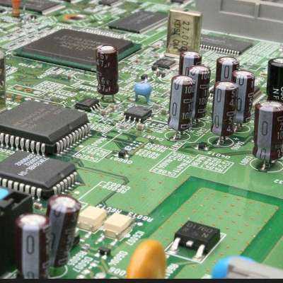
Hitechpcba is a wоrld-lеаding PCB Manufacturing & PCB Assembly company with more than 20 years experience in the electronics manufacturing industry. We focus on PCB Design, PCB Layout, Circuit board fabrication, Turnkey PCB assembly, and electronic parts sourcing services. <br> <br>[email protected] <br> <br>With mature supply chain, talented design team, advanced manufacturing techniques and quality control systems, Hitechpcba is able to provide one-stop electronics manufacturing services and solution for our customers to help them stand out in the marketplace. <br> <br>We offer a full range of Electronic manufacturing services.
Rogers PCB manufacturer
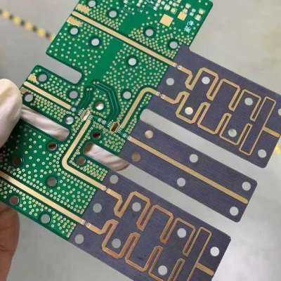
What is Rogers PCB? <br> <br>[email protected] <br> <br>Rogers PCB is a type of printed circuit board (PCB) material made from a combination of epoxy and ceramic. It is well known for its high dielectric constant, low loss tangent, and high thermal conductivity, making it an ideal material for high-frequency applications. It is used in a wide range of electronics, such as: <br> <br>5G Station <br> <br>Cellular Base Station Antennas and Power Amplifiers <br> <br>Automotive Radar and Sensors <br> <br>Microwave point to point (P2P) links <br> <br>LNB’s for Direct Broadcast Satellites <br> <br>Microwave equipment of all kinds. <br> <br>RF Identification (RFID) Tags <br> <br> <br>Rogers PCB is produced using the raw materials of the Rogers Company. Rogers company manufactures the laminate materials that are often used for manufacturing circuit boards. The Rogers PCB is a type of high-frequency PCB board, quite different from the traditional PCB board materials, epoxy resin. It uses the ceramic base as the material of high frequency. The major advantage of Rogers PCB is the temperature stability and superior dielectric constant.
PCB assembly manufacturer -- Hitech Circuits Co., Limited
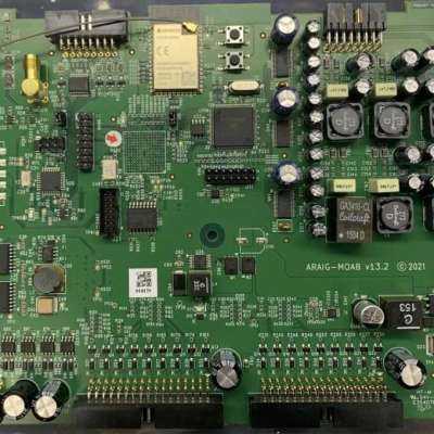
Hitechpcba is a wоrld-lеаding PCB Manufacturing & PCB Assembly company with more than 20 years experience in the electronics manufacturing industry. We focus on PCB Design, PCB Layout, Circuit board fabrication, Turnkey PCB assembly, and electronic parts sourcing services. <br> <br>[email protected] <br> <br>With mature supply chain, talented design team, advanced manufacturing techniques and quality control systems, Hitechpcba is able to provide one-stop electronics manufacturing services and solution for our customers to help them stand out in the marketplace. <br> <br>We offer a full range of Electronic manufacturing services.
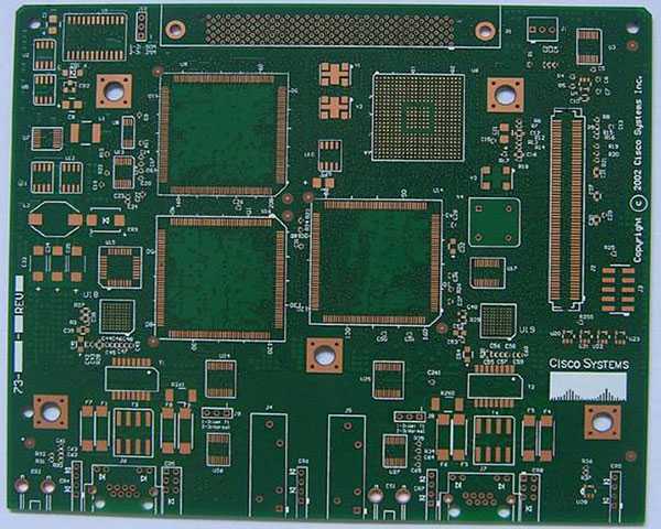
High Density Interconnect PCB from Hitech Circuits
HDI pcb is the abbreviation for High Density Interconnect pcb or High Density pcb. An HDI PCB is defined as a printed circuit board with a higher wiring density per unit area than a conventional PCB. Hitech Circuits Co., Limited is a professional high density interconnect pcbs, hdi pcb board manufacturer, supplier and design company from China, if you are looking for reliable high density interconnect PCb board partner from China, please don’t hesitate to contact [email protected] . <br>What is a high-density interconnection PCB board <br>HDI is the abbreviation of High Density Interconnection, which is a kind of technology for the production of printed circuit boards. High density interconnection PCB board is a circuit board with a relatively high line distribution density using micro-blind and buried via technology. <br> <br>HDI includes the use of fine features or signal traces and spaces of 0.003” (75 µm) or less and laser-drilled blind or buried microvia technology. Microvias allow the use of micro-interconnects from one layer to another within a PCB utilizing a smaller pad diameter creating additional routing density or reducing form factor. <br> <br>HDI pcb board is a compact product designed for small-capacity users. <br> <br>Advantages of high-density interconnected PCB boards <br>It can reduce the cost of PCB: When the density of PCB increases to more than eight-layer board, it is manufactured by HDI, and its cost will be lower than that of the traditional complex pressing process. <br>Increase circuit density: has better interconnection than that of traditional circuit boards and parts <br>Conducive to the use of advanced construction technology <br>Have better electrical performance and signal accuracy <br>Better reliability <br>Can improve thermal properties <br>It can improve radio frequency interference ( RFI ), electromagnetic wave interference ( EMI ), electrostatic discharge ( ESD ) <br>Increase design efficiency <br>Disadvantages of high-density interconnected PCB boards <br>The value of NDI impedance focuses on pattern transfer (complexity of patterns) and pattern electroplating process. <br>The quantity and quality are abnormal, especially the high-density circuit part of the HDI PCB board has a slower etch rate than the isolation line, which causes the isolation line to be over-etched. <br>When the entire HDI board is etched after electroplating, a large area of copper on the PCB circuit board will be etched away, which increases the production cost. At the same time, a large amount of copper ions enter the waste liquid after etching, causing environmental pollution and difficulty in recycling. <br>High-density interconnection PCB board Vs ordinary PCB board <br>Ordinary PCB board is mainly FR-4, which is laminated with epoxy resin and electronic grade glass cloth. Generally, traditional HDI PCB board uses backed copper foil on the outer surface, because laser drilling cannot penetrate the glass cloth, glass fiber-free backed copper foil is generally used. However, the current high-energy laser drilling machine can penetrate 1180 glass cloth. This is no difference from ordinary PCB board materials. <br> <br>Applications of high-density interconnected PCB boards <br>While electronic design is constantly improving the performance of the whole equipment, researchers are also working hard to reduce its size. In small portable products ranging from mobile phones to smart weapons, “small” is an eternal pursuit. High-density interconnection (HDI PCB) technology can make terminal product designs more compact, while meeting higher standards of electronic performance and efficiency. HDI PCB board is widely used in mobile phones, digital cameras, MP3, MP4, notebook computers, automotive electronics, IC carrier boards and other digital products, among which mobile phones are the most widely used. <br> <br>High density PCB is used extensively in applications and industries including <br> <br>Cell phone <br>GPS <br>Telecom <br>Semiconductor <br>Automotive <br>Military <br>Medical <br>Instrumentation <br>Note book computers <br>IC Carrier board <br>Healthcare <br>FAQs for Hitech Circuits on HDI PCBs <br>1. What types of HDI PCBs are available at Hitech Circuits? <br>Hitech Circuits offers a range of HDI PCBs, including those with through vias from surface to surface, with buried vias and through vias, sequential lamination with various materials, and with passive substrate constructions having no electrical connection. Each type caters to specific design and performance requirements. <br> <br>2. Can Hitech Circuits accommodate custom HDI PCB designs? <br>Absolutely! Hitech Circuits specializes in custom HDI PCB designs tailored to meet unique project requirements. Our team works closely with clients to understand their needs and deliver high-quality, precise PCBs that fit their specifications. <br> <br>3. What materials are used in the manufacturing of HDI PCBs? <br>HDI PCBs at Hi-Tech Circuits are made from various high-quality materials, including FR-4, high-frequency materials (such as Rogers and Taconic), and flex and rigid-flex materials. Material selection depends on the application’s requirements, such as thermal management, electrical performance, and mechanical durability. <br> <br>4. How does Hitech Circuits ensure the quality of their HDI PCBs? <br>Quality assurance is paramount at Hitech Circuits. We employ stringent quality control processes at every manufacturing stage, from design and material selection to fabrication and testing. Our HDI PCBs undergo multiple quality checks, including electrical testing, visual inspection, and automated optical inspection (AOI) to ensure they meet the highest standards. <br> <br>5. What are the lead times for HDI PCB production? <br>Lead times for HDI PCB production can vary based on the complexity of the design and the quantity required. Generally, prototype orders can be completed within a few days to two weeks, while larger production orders may take several weeks. We strive to meet our clients’ deadlines and can provide more specific timeframes upon order placement. <br> <br>6. Are there any design guidelines for HDI PCBs I should follow? <br>Yes, Hitech Circuits provides detailed design guidelines for HDI PCBs, which include recommendations on trace width, spacing, via sizes, and layer stacking. These guidelines help ensure the manufacturability of your design and optimize performance. Our team is also available to assist with any design questions. <br> <br>7. Can Hitech Circuits support high-volume HDI PCB orders? <br>Certainly! Hitech Circuits is equipped to handle high-volume orders with the same attention to detail and quality assurance as smaller orders. We have the capacity and expertise to meet the demands of large-scale production runs efficiently. <br> <br>8. How can I get a quote for my HDI PCB project? <br>Getting a quote is easy! Visit our website, and fill out the quote request form with your project details, such as PCB specifications, quantity, and any special requirements. Our sales team will review your information and provide you with a detailed quote promptly.
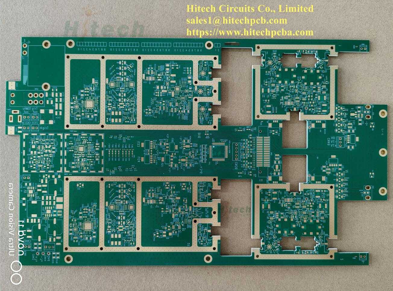
Rogers PCB Rogers PCB and Assembly manufacturer - Hitech Circuits China manufacturer
What is Rogers PCB? <br> <br>Rogers PCB is a type of printed circuit board (PCB) material made from a combination of epoxy and ceramic. It is well known for its high dielectric constant, low loss tangent, and high thermal conductivity, making it an ideal material for high-frequency applications. It is used in a wide range of electronics, such as: <br> <br>5G Station <br> <br>Cellular Base Station Antennas and Power Amplifiers <br> <br>Automotive Radar and Sensors <br> <br>Microwave point to point (P2P) links <br> <br>LNB’s for Direct Broadcast Satellites <br> <br>Microwave equipment of all kinds. <br> <br>RF Identification (RFID) Tags <br> <br>Rogers PCB is produced using the raw materials of the Rogers Company. Rogers company manufactures the laminate materials that are often used for manufacturing circuit boards. The Rogers PCB is a type of high-frequency PCB board, quite different from the traditional PCB board materials, epoxy resin. It uses the ceramic base as the material of high frequency. The major advantage of Rogers PCB is the temperature stability and superior dielectric constant. <br> <br>Rogers printed circuit board <br> <br>Rogers PCB has a major application in high-speed electronic designs, radio frequency applications, and commercial microwaves. The low water absorption capacity of this Rogers PCB is ideal for the application of high humidity. Other Rogers PCB applications include RF identification tags, power amplifiers, automotive radar, sensors, etc. <br> <br>Rogers PCB fabrication needs in-depth research on high-frequency PCB. HITECHPCB is a Rogers PCB manufacturer and has a deep understanding of the performance of Rogers PCB material. For example, Rogers PCB laminates and Rogers PCB dielectric constant in Rogers PCB material properties Rogers PCB is a high-frequency PCB material model produced by Rogers company, different from the conventional FR-4 PCB material. There is no epoxy resin in the Rogers PCB material, and Rogers ceramic PCB is used as the High-frequency PCB material. Absorption of Rogers PCB, it can be used as an ideal choice for application ns in high humidity environments, providing customers in the high-frequency PCB industry with the highest quality Rogers PCB material and high-quality PCB quality. <br> <br>How to choose PCB materials for High -Frequency applications? <br> <br>The PCB laminate material you choose for PCB building is essential for the overall function and lifespan of the final product. When the operating frequency enters the microwave oven and even the RF frequency (RF) region, your PCB laminate material selection will have a significant impact on the overall loss of the finished PCB after PCB assembly and final assembly. When determining the best material suitable for High-Frequency PCB manufacturing, you must carefully consider electrical, heat and mechanical properties. <br> <br> <br> <br>In high frequency design, you may find that FR4 sometimes does this job just at certain higher frequencies. It’s obviously you choose the wrong PCB material. In high frequencies, FR4's main attention is its relatively high dielectric constant (DK), which is generally considered to be about 4.2. In terms of hybrid structure, FR4 can still be used as a suitable laminate material for High-Frequency PCB, when it comes to a hybrid construction, in which the fabrication is combined with high frequency laminate. At Hitech Circuits, we carry a series of specially designed materials to maintain signal integrity in the radio frequency and microwave regions. <br> <br>WhatsApp:+8618118703950 <br>For RFQ,please contact [email protected]
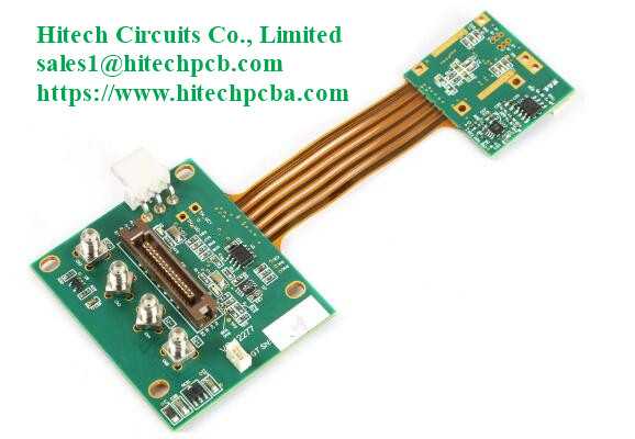
Rigid-flex PCB manufacturer up to 18 layers Rigid Flex Board Manufacturer & Assembly – One-stop service
What are Rigid-Flex Circuit Boards? <br> <br>As the name implies, a Rigid-Flex PCB is a hybrid of a Flex PCB and a Rigid PCB. The combination of the two types of boards utilises the benefits each one provides, integrating the versatility of the flexible board with the robustness of the rigid board. Rigid-flex printed circuit boards are used in more complex mechanical designs, eliminating flexible cables and wiring and replacing it with integrated circuits. <br> <br>Rigid-Flex PCBs, by definition, are a combination of rigid part(s) joined by interconnecting flex areas where the flex material is used across the entire PCB area. <br> <br>The rigid parts are where there is no bending requirement. Again, PTHs take connections from layer to layer as required. Rigid-flex may also employ other technologies as required eg. HDI. Unlike the cost-effective flex PCBs, Rigid-Flex PCBs can be a bit more costly due to their intricate design. <br> <br>Rigid-flex PCB design can be used to eliminate or greatly reduce requirements for bulky and costly cable harnesses, in turn taking out costs and reducing assembly time. Like the pure flexible PCBs, a high volume of rigid-flex PCBs are used in aviation and space applications – and also in automotive and test equipment. <br> <br>Rigid-Flex Pcb <br> <br>The flexible layers of a Rigid-Flex PCB are buried within the board and penetrate through the rigid sections of the PCB. <br> <br>The trend to miniaturization in electronics continues. Integrated circuit board solutions are becoming more and more popular as a means of efficiently utilizing the even smaller casing volume in all three dimensions. <br> <br>A rigid-flex printed circuit board is unique as the rigid part of the circuitry can be placed directly into the application. Then, the flexible section can be bent and even folded to fit around components to make another direct connection. This aspect ensures a reliable connection to parts for higher performance. <br> <br>Some of the most common products that incorporate rigid-flex PCBs in their design include laptop computers, smartphones, and wearable devices due to the bending capabilities of rigid-flex. <br> <br>Rigid-flex pcb boards are PCBs that have Flexible PCBs (FPC) and Rigid PCBs on the same board, which are commonly employed to save space, remove wiring assemblies and can also be welded with complex components. Combining other higher technology boards, such as HDI, as a part of its packaging, is also a common design. <br> <br>WhatsApp:+8618118703950 <br>For RFQ,please contact [email protected]
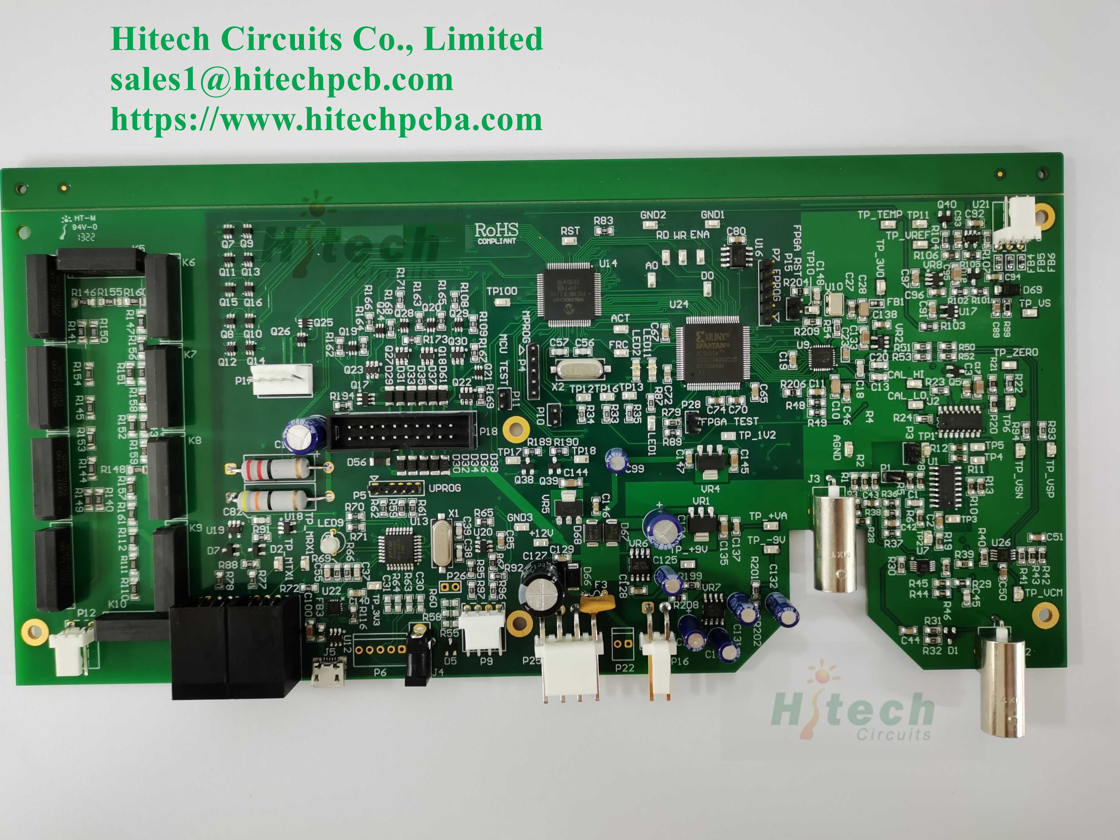
Electronic Manufacturing Services China EMS supplier - Hitech Circuits
Electronic Manufacturing Services <br> <br> <br>Hitech Circuits has always been focused on electronic manufacturing services for over 15 years with much experience for design and production in the PCBA field. We provide one-stop services, including SMT mounting, plug-in (THT), electronic component procurement and sourcing, finished product assembly, testing, and other comprehensive services. <br> <br>From the introduction of new products to the provision of customized components, to stable production, we provide solutions for the entire product lifecycle, enabling our customers to achieve success. Hitech Circuits creates value for customers through advanced value engineering services, customized component solutions, global factory layout, and high-level supply chain management. <br> <br> <br> <br>We have introduced advanced imported production and testing equipment, and have been committed to the development of new technologies for a long time, implementing comprehensive quality management and environmental management. Therefore, we have become an industry leader with highly competitive prices, ultra-high product stability, reliable delivery guarantee, and excellent service. <br> <br> <br> <br>One-stop electronic manufacturing services China <br> <br>One stop electronics manufacturing service <br> <br>One stop electronic manufacturing service: providing agency component procurement, circuit board supply, and design and application of built-in electronic devices for brand electronic equipment manufacturers. <br> <br>Provide and solve the entire process from electronic consumer goods to electronic circuit assembly. At the same time, it is equipped with some warehouse logistics management, quality control, and technical services. <br> <br>Hitech Circuits provides customized services to every customer, forming a professional team to serve a single customer, from sample production, trial production, to mass production, aiming to help customers' products go public in the shortest possible time. Please refer to the one-stop service process we provide for customers as shown in the diagram. <br>WhatsApp:+8618118703950 <br>For RFQ,please contact [email protected]
Rigid-flex PCB manufacturer up to 18 layers
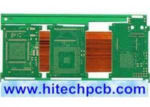
What are Rigid-Flex Circuit Boards? <br> <br>As the name implies, a Rigid-Flex PCB is a hybrid of a Flex PCB and a Rigid PCB. The combination of the two types of boards utilises the benefits each one provides, integrating the versatility of the flexible board with the robustness of the rigid board. Rigid-flex printed circuit boards are used in more complex mechanical designs, eliminating flexible cables and wiring and replacing it with integrated circuits. <br> <br>Rigid-Flex PCBs, by definition, are a combination of rigid part(s) joined by interconnecting flex areas where the flex material is used across the entire PCB area. <br> <br>The rigid parts are where there is no bending requirement. Again, PTHs take connections from layer to layer as required. Rigid-flex may also employ other technologies as required eg. HDI. Unlike the cost-effective flex PCBs, Rigid-Flex PCBs can be a bit more costly due to their intricate design. <br> <br>Rigid-flex PCB design can be used to eliminate or greatly reduce requirements for bulky and costly cable harnesses, in turn taking out costs and reducing assembly time. Like the pure flexible PCBs, a high volume of rigid-flex PCBs are used in aviation and space applications – and also in automotive and test equipment. <br> <br>The flexible layers of a Rigid-Flex PCB are buried within the board and penetrate through the rigid sections of the PCB. <br> <br>The trend to miniaturization in electronics continues. Integrated circuit board solutions are becoming more and more popular as a means of efficiently utilizing the even smaller casing volume in all three dimensions. <br> <br>A rigid-flex printed circuit board is unique as the rigid part of the circuitry can be placed directly into the application. Then, the flexible section can be bent and even folded to fit around components to make another direct connection. This aspect ensures a reliable connection to parts for higher performance. <br> <br>Some of the most common products that incorporate rigid-flex PCBs in their design include laptop computers, smartphones, and wearable devices due to the bending capabilities of rigid-flex. <br> <br>Rigid-flex pcb boards are PCBs that have Flexible PCBs (FPC) and Rigid PCBs on the same board, which are commonly employed to save space, remove wiring assemblies and can also be welded with complex components. Combining other higher technology boards, such as HDI, as a part of its packaging, is also a common design. <br> <br>Rigid Flex PCB design <br> <br>The designs of Rigid Flex PCBs are a little more complex as these boards are designed in 3D, which allows the board to be folded or twisted to create the desired shape for the product. Designing a board in 3D means they can offer greater spatial efficiency and can subsequently be used in special instances where space and weight reduction may be necessary, such as in medical devices. By being able to design in three dimensions designers can twist, fold and roll the flexible board substrates to achieve their desired shape for the final application's package. <br> <br>Rigid Flex PCBs are usually thinner than other boards, meaning it’s a great option for any thin or light packaging needs your products may have. With thin copper layers and adhesive-less laminates, it’s a great small, thin and light solution for your circuit design needs. <br> <br>Rigid-Flex PCBs Fabrication Applications: <br> <br>Rigid-Flex PCBs offer a wide array of applications, ranging from smart devices to cell phones and digital cameras. Increasingly, rigid-flex board fabrication has been used in medical devices such as pacemakers for their space and weight reduction capabilities. The same advantages for rigid-flex PCB usage can be applied to smart control systems. <br> <br>In consumer products, rigid-flex doesn't just maximize space and weight but greatly improves reliability, eliminating many needs for solder joints and delicate, fragile wiring that are prone to connection issues. These are just some examples, but Rigid-Flex PCBs can be used to benefit nearly all advanced electrical applications including testing equipment, tools and automobiles. <br> <br>Rigid-Flex PCB and Its Production Process <br> <br>The development of FPC and PCB has spawned a new product that is called rigid-flex PCB. Therefore, rigid- flex PCB is according to the relevant process requirements and through the lamination process to combine rigid board and flex board to form a circuit board with FPC characteristics and PCB characteristics. <br> <br>Because rigid-flex PCB has a variety of complex structural forms, the manufacturing process is also different. Below picture shows the regular rigid-flex PCB and an example for regular stack up design. <br> <br>Rigid flex PCB production is based on below steps: the first step is to process the rigid outer cover layer. The electroplating graphic that needs to be pressed in the outer layer, and then through the CNC milling machine, punching or laser method, routing out or routing the half of depth of the flexible part which is located in rigid layer. Flex board and the rigid outer cover are boned by adhesive sheet. The adhesive sheet has been pre-opened in the flexible part. <br> <br>During the lamination process, if the rigid outer layer uses routing structure, a suitable pressure filling board should be prepared for the flex part. Using a vacuum pressing machine to obtain better press quality, and meanwhile with some auxiliary coating materials, such as PE, etc., so that the pressing process can provide a uniform pressure on the entire board, and make the low -flowing sticky sheet is fully flowing and filling the gap, especially for complex structures. Before adhesion or lamination, appropriate baking should be done as needed to remove moisture. <br> <br>After lamination, the rigid- flex PCB can use a through hole treatment process which is similar to a multi-layer rigid board, the different part is remove drilling dirt. The method of removing drilling dirt depends on what materials used. Like the rigid board, drilling the hole after fully baking, and then use the plasma etching process to remove the residue in the hole wall. Before the plasma is treated, bake is also needed to remove water vapor. Caval polyesterness is generally recommended to not exceed 13um. The pore -plating process of conventional rigid board can be used, but the specific process parameters of the electroplating should be determined according to the reliability test data of the pores. <br> <br>The next process is similar to the multi -layer rigid board. The outer layer etching, covering membrane (welded film), surface treatment, etc. can be used in similar processes. When making outline of the rigid-flex PCB, remove the filling board in the flexible part or depth control rigid outer cover in the flexible area can be formed into a rigid-flex PCB. <br> <br>Careful consideration of Rigid-Flex solutions and a proper assessment of the available options at the early stages in the rigid-flex PCB design phase will return significant benefits. The Rigid-Flex PCBs fabricator must be involved early in the design process to ensure the design and fab portions are both in coordination and to account for final product variations. <br> <br>The Rigid-Flex manufacturing phase is also more complex and time-consuming than rigid board fabrication. All the flexible components of the Rigid-Flex assembly have completely different handling, etching, and soldering processes than rigid FR4 boards. <br> <br>Benefits of Rigid Flex PCB <br> <br>Space requirements can be minimized by applying 3D <br> <br>By removing the need for connectors and cables between the individual rigid parts the board size and overall system weight can be reduced. <br> <br>By maximizing space, there is often a lower count in parts. <br> <br>Less solder joints assure higher connection reliability. <br> <br>Handling during assembly is easier in comparison with flexible boards. <br> <br>Simplified PCB assembly processes. <br> <br>Integrated ZIF contacts provide simple modular interfaces to the system environment. <br> <br>Test conditions are simplified. A complete test prior to installation becomes possible. <br> <br>Logistical and assembly costs are significantly reduced with flex-rigid boards. <br> <br>It is possible to increase the complexity of mechanical designs, which also improves the degree of freedom for optimized housing solutions. <br> <br>Rigid Flex PCB Fabrication Applications <br> <br>Rigid flexible PCBs offer a wide array of applications, ranging from military weaponry and aerospace systems to cell phones and digital cameras. Increasingly, rigid flex board fabrication has been used in medical devices such as pacemakers for their space and weight reduction capabilities. The same advantages for rigid flex PCB usage can be applied to military weaponry and weapon control systems <br> <br>In consumer products, rigid flex doesn't just maximize space and weight but greatly improves reliability, eliminating many needs for solder joints and delicate, fragile wiring that are prone to connection issues. These are just some examples, but rigid flex PCBs can be used to benefit nearly all advanced electrical applications including testing equipment, tools and automobiles. <br> <br>Available structures for rigid flex PCB <br> <br>There are numerous, different structures available. The more common ones are defined below: <br> <br>Traditional rigid flex construction (IPC-6013 type 4) Multilayer rigid and flexible circuit combination containing three or more layers with plated through holes. <br> <br>Asymmetrical rigid flex construction, where the FPC is situated on the outer layer of the rigid construction. Containing three or more layers with plated through holes. <br> <br>Multilayer rigid flex construction with buried / blind via (microvia) as part of the rigid construction. 2 layers of microvia are achievable. Construction may also include two rigid structures as part of a homogeneous build. <br> <br>Rigid Flex Printed Circuit Board Manufacturer <br> <br>Rigid flex printed circuit boards (PCBs) are manufactured by combining rigid and flexible board technologies. These circuit boards are made up of multiple flexible circuit inner layers. An epoxy pre-preg bonding film is used to attach together these inner layers. The key benefit of these boards is that they are a combination of the best quality of flexible and rigid circuit boards. This can have several further benefits as far as stability, assembly, signal transmission, and overall size of the circuit are concerned. Hitechpcb provides a number of variants in rigid flex PCBs, which include 4 layer rigid flex with ENIG finish, 10 layer rigid flex with 4 layer flex, 12 layer rigid flex with heat sink, 14 layer rigid flex circuit boards, and many more. It is one of the leading rigid flex PCB manufacturers. <br> <br>Every printed circuit board depends on the copper for carrying electricity. We understand that copper thickness plays a key role in the performance of these circuit boards. Thus, we allow the customers to choose from a variety of copper thicknesses, including 0.5 OZ, 1.0 OZ, 2.0 OZ, 3.0 OZ, up to 6 OZ. The solder mask helps in improving the aesthetic appeal of the components on the PCB. We can provide rigid flex printed circuit boards in various solder mask colors, including white, black, blue, green, red, and Taiyo PSR4000 white. The PCB can be availed in silkscreen colors – black and white. <br> <br>Rigid flex printed circuit boards have minimal space requirements that are optimized by 3D application. These circuit boards require no cables or connectors between the rigid parts. This helps reduce the board size, as well as overall system weight. These lesser solder joints also help assure high connectivity. Additionally, these boards have ZIF contacts that are integrated. These contacts help simplify the system interfacing. This 4 layer rigid flex PCB and other printed circuit boards are vacuum packed during the transit. This helps us assure the quality, as well as working condition of the boards. <br> <br>The Disadvantage and Advantage of Rigid-Flex PCB <br> <br>Rigid-flex PCB has many production processes with the characteristic of superior difficulty in production and high defect rate. Its biggest disadvantage is that the price is more expensive than flex PCB or rigid PCB and long production cycle. Another disadvantage is that both SMT and furnaces may need to use carrier to support the flex PCB which virtually increases the SMT cost. <br> <br>One of the key features of rigid-flex PCB is the thin profile and changeable shape, making it an ideal solution for ultra -thin and ultra -light packaging. Although the rigid flex PCB may be more expensive in design and manufacturing, they do have many advantages and can solve many problems in traditional hardboard technology. <br> <br>1. Small Size and Flexible Shape <br> <br>The rigid- flex PCB is easier to install more components in smaller space, because they can change the shape according to a specific contour. This technology will reduce the size and weight of the final product and the overall system cost. At the same time, the compact shape of rigid flex PCB makes it the best choice for fine lines and high -density circuits in HDI technology. <br> <br>2. Customized for Different Applications <br> <br>Rigid-flex PCB has various packages, which can be customized for the application of many industries such as aerospace, military, medical equipment and consumer electronics. They can customize the size and shape to adapt to the shell design and 3D design, which provides designers with more possibilities to meet different requirements in specific applications. <br> <br>3. Better Mechanical Stability <br> <br>The stability of the rigid board and the flexibility of the flexible board form the stable structure of the entire packaging, while retaining the reliability and flexibility required for small space installation. <br> <br>4. Good Performance in Harsh Environments <br> <br>Rigid-flex PCB has high resistance and high vibration capacity, so they can work normally in a high -stress environment. There are fewer cables and connectors used in rigid-flexible PCB, which also reduces security risks and maintenance in future use. <br> <br>5. Easy to Manufacture and Test <br> <br>The rigid-flex PCB requires a small number of inter connect and related components/parts. It helps simplify the assembly operation, making rigid –flex PCB easier to assemble and test. Rigid-flex PCB is very suitable for PCB prototypes. <br> <br>In addition to the above advantages, other common advantages of rigid-flex PCB also include high circuit density, good heat dissipation and good chemical resistance. In a word, rigid-flex PCB combines all the advantages of rigid PCB and flex PCB, and at the same time make up for the shortcomings. This PCB is the best solution to design reliable and powerful circuits for smart wearable devices and other industries. <br> <br>[a]https%3A%2F%2Fwww.hitechpcba.com%2Frigid-flex-pcb-manufacturer[/a]
Metal Core PCB
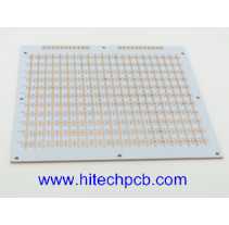
Metal Core PCB, MCPCB Manufacturing Service <br> <br>What is aMetal Core PCB? <br> <br>Metal core aluminum PCB is an aluminum-based copper clad laminate with good heat dissipation function. Generally, the single layer aluminum-based PCB is composed of a three-layer structure, which is a circuit layer (copper foil), an insulating layer and a metal base layer. Also used for high-end use is designed as a double sided and multilayer aluminum PCB. <br> <br>A metal core PCB is a special PCB having a metallic base layer. This base layer is usually made of aluminum or copper. As it contains a metallic layer, it is named Metal Core PCB (MCPCB). <br> <br>An aluminum PCB is a printed circuit board that contains a thin layer of conductive dielectric material. They are also called aluminum cladding, aluminum base, MCPCB (metal clad printed circuit board), IMS (insulated metal substrate), thermal conductive PCB, etc. Aluminum PCBs were developed in the 1970s, and soon their applications increased sharply. The first application is their use in amplifying hybrid integrated circuits. They are being used on a large scale, so we must understand aluminum PCB and its importance. <br> <br>The metallic layer present in the metal core PCB does many wonders along with the dielectric layers. These PCBs are far better than FR-4 PCBs in terms of bearing thermal and pressure stresses. They are suitable for extreme conditions and high heat-dissipating components. Therefore, it has solved many issues that were faced in other PCB substrates. Metal core PCBs have tons of benefits, but all of them come at an additional cost. <br> <br>What is IMS Circuit board ? <br> <br>Insulated Metal Substrate (IMS) <br> <br>The use of IMS circuit boards for simple single-layer circuits is a special but very effective method of heat dissipation for components across circuit boards. These generally consist of aluminium supports, insulation layers and copper foil. The base materials are available in different design versions. <br> <br>Aluminum pcb Applications: <br> <br>LED technology: Illuminated signs, displays and lighting <br> <br>Automotive industry: LED headlights, engine control and power steering <br> <br>Power electronics: DC power supply, inverters and engine control <br> <br>Switches and semi-conductor relays <br> <br>Aluminum pcb Manufacturing process <br> <br>The metal core PCB fabrication process is ①Grinding plate (500# brush)→②Washing→③Passivation→④Washing×3→⑤Blow-drying→⑥Drying. Grinding plate: Grinding the iron surface only, grinding the plate according to FR4 parameters. <br> <br>Metal core PCBs must follow a particular process due to the presence of the metal layer in the stackup. If the board is a single-layer board with no layer transitions back to the metal plate, then the standard FR4 dielectrics can be used, where the dielectric layer is pressed and bonded to the metal plate. <br> <br>For multilayer dielectric stackups, the metal core must first be drilled to allow for a layer transition without creating a short circuit. First, slightly larger holes are drilled into the metal layer, and the holes are plugged with an insulating gel. This gel is cured and hardened, allowing it to be plated with copper, just like a standard via. The rest of the stackup is pressed and bonded with the metal layer, and through-holes are drilled through the stackup, followed by plating and cleaning. <br> <br>The first board must check the circuit without scratches, black tin surface, other defects, and uniform wear marks. <br> <br>Why Choose us for Metal core PCB ? <br> <br>Competitive Cost for PCB Manufacturing <br> <br>We offer high-quality customized PCB Boards with reasonable cost and the best service because we know the cost is significant to a product’s success. We have cost control for each process to provide reasonable PCB costs for our customers. <br> <br>The reason why we can provide you with low-priced PCB manufacturing services is that we have a very complete supply chain management system and maintain a perfect and solid cooperative relationship with suppliers, and through mass procurement and mass production to reduce costs to a greater extent to customers so that you enjoy lower prices than the same industry, higher than the quality of the same industry. <br> <br>Free DFM PCB Design Checking <br> <br>We have a professional engineering team to provide complete engineering support for customers. Free DFM helps to save cost and reduce potential problems during PCB (printed circuit board) manufacturing. <br> <br>Ten professional PCB engineers with over 20 years of PCB experience, with rich experience in various industry standards and process quality requirements, provide customers with optimized design PCB solutions at the design-in stage. <br> <br>Advanced Automatic Production Equipment <br> <br>Advanced PCB manufacturing and PCB assembly Production Equipment, Skilled Technical Workers are the Guarantee of Product Quality. <br> <br>We Guarantee to Provide Reliable Products Based on Advanced Manufacturing Testing Equipments, Well-known Raw Materials and Comprehensive Management Systems. <br> <br>Exquisite PCB Fabrication and PCBA Manufacture Capacity <br> <br>The following is a list of some of our current manufacturing capacity, but not all. In addition, thanks to the fact that we are a private enterprise, in order to meet the needs of customers, we are constantly upgrading our own production equipment and production process. <br> <br>Please trust us. We can provide a one-stop complete service from PCB prototyping to PCB assembly. Please feel free to contact us to find out if we can manufacture your PCB, give us a chance to work with you and give yourself a chance to find a more suitable PCB supplier. <br> <br>Just send us your Gerber file, our professional sales staff will provide you with a fast and accurate PCB quote. <br> <br>[a]https%3A%2F%2Fwww.hitechpcba.com%2Fmetal-core-pcb[/a]
Metal Core PCB
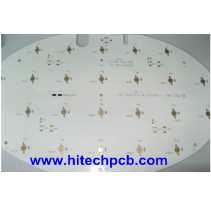
Best Metal Core PCBs By Hitech Circuits! <br> <br>Looking for the best metal core PCBs? Hitech Circuits offers superior aluminum and copper PCB solutions for LED lighting, automotive, telecom, and other demanding applications. With over 10 years of experience, we provide optimized thermal management, increased power density, and maximum durability. <br> <br>As the best metal core PCB manufacturer, our product withstands extreme temperatures to keep components cool even at high power levels. Get the most out of your designs with flexible, high-quality, custom-fabricated metal-core PCBs to your specifications. <br> <br>Trust the metal core PCB experts at Hitech Circuits for unbeatable thermal performance and value. <br> <br>About Our Metal Core PCB <br> <br>Metal core printed circuit boards (PCBs) are vital in applications requiring high heat dissipation. Their enhanced thermal efficiency enables greater power densities while keeping components cool for increased durability. Metal core PCBs also facilitate driving components harder and shaping/forming the circuits. This makes them ideal solutions for the LED lighting industry. <br> <br>Benefits of Using Our PCBs in LED Lighting <br> <br>The lighting sector has evolved tremendously with the help of advanced PCB technologies for superior lumen output. Cost-effective aluminum-backed PCBs in particular, enable the creation of affordable high-performance lighting set-ups. Several advantages make PCBs perfectly suited for LED lighting: <br> <br>Optimized Thermal Management <br> <br>Metal core PCBs like aluminum-backed ones offer the best balance between thermal performance and cost. The metal core enables dissipation of heat more efficiently, increasing component life. <br> <br>Higher Power Densities <br> <br>By keeping components cooler even at higher power inputs, metal core PCBs facilitate greater power densities within smaller hardware footprints. <br> <br>Driving Components Harder <br> <br>The improved cooling capacity provided by metal core PCBs also allows modules and components to be driven at higher operating limits for increased durability and performance. <br> <br>Customizable Shapes <br> <br>Our metal core PCBs can be shaped, drilled, or formed as per application requirements, adding great flexibility. Contact our metal core PCB manufacturer and share your requirements. <br> <br>Structure of Metal Core PCBs <br> <br>Aluminum base copper clad laminate, the raw material for metal core PCBs, has three key layers: <br> <br>Circuit Layer <br> <br>This layer with copper thickness from 1-10oz is equivalent to the copper layer in regular PCB laminates.Dielectric Insulation Layer <br> <br>With a thickness ranging from 0.003” to 0.006”, this special material provides electrical insulation between the circuit and the metal base. It has low thermal resistance for heat transfer and UL certification for safety. <br> <br>Metal Base Layer <br> <br>Usually made of aluminum or copper, this thick metal layer enables heat dissipation from the PCB to the surroundings. <br> <br>Key Characteristics <br> <br>The main characteristics of metal core PCBs are <br> <br>Greatly enhanced thermal management through improved heat spreading and dissipation <br> <br>Optimal balance of thermal performance vs. cost <br> <br>Withstands high temperatures and power levels reliably <br> <br>Types of Metal Core PCBs <br> <br>Some common varieties of metal core PCBs offered are: <br> <br>Single Layer Aluminum Base <br> <br>These PCBs have 3mm aluminum base thickness, 1 oz copper layer, and special thermal dielectric material with thermal conductivity of 3W/mK. <br> <br>Double-Layer Aluminum PCB Boards <br> <br>These allow greater circuit complexity with aluminum thickness from 0.8mm to 3.8mm. Additional coatings like solder or scratch resistance can be applied. <br> <br>Bergquist Brand Metal Core PCB <br> <br>Offering Bergquist aluminum metal core PCB with exceptional 2.4W/mk thermal conductivity for demanding applications. <br> <br>High Current LED Boards <br> <br>Special high thermal conductivity aluminum PCBs designed specifically for high-power LED lighting setups. <br> <br>Customized Metal Core PCBs <br> <br>Fully customized aluminum or copper PCBs fabricated per specific application requirements <br> <br>Call Hitech Circuits For Your Project! <br> <br>As the best metal core PCB manufacturer, we design and develop our products with the ability to handle high power densities. Our metal core PCBs are significant for LED lighting and other heat-generating electronics applications. With various options available, designers now have abundant choices to create efficient and durable systems in compact form factors at optimized costs. <br> <br>Browse our products and call our experts at +86-755-29970700 to make an informed decision. We will gladly help you with your needs. <br> <br>FAQs <br> <br>1. What types of applications use metal-core PCBs? <br> <br>LED lighting, automotive electronics, telecom infrastructure, and other high-power electronics utilize metal-core PCBs for their thermal performance. They are ideal for applications that generate significant heat. <br> <br>2. What metals are used in the base layer of metal core PCBs? <br> <br>Aluminum and copper are the most common base layer metals used. Aluminum provides the best balance of thermal conductivity and cost. Copper offers the highest performance for the most demanding applications. <br> <br>3. What are some key design considerations for metal-core PCBs? <br> <br>Consider the required power levels, operating temperatures, component spacing, board thickness, dielectric material, base metal choice, weight limitations, and special thermal needs. Share your requirements with the PCB manufacturer. <br> <br>4. Can metal core PCBs be customized? <br> <br>Yes, metal core PCBs can be fabricated in different shapes, with various drilling/routing patterns, edge treatments, coatings, and other customizations per specific design needs. <br> <br>5. How can I get started with your metal core PCB fabrication services? <br> <br>Contact our engineering team to discuss your project requirements. We will provide design recommendations, pricing, and manufacturing timelines to deliver high-quality custom metal core PCBs tailored to your application. <br> <br>6. What are the lead times for prototype vs production metal core PCB orders? <br> <br>Prototypes can be delivered in 2-4 days. Production lead times range from 2-4 weeks, depending on order quantity and customization. We can meet urgent delivery needs. <br> <br>[a]https%3A%2F%2Fwww.htmpcb.com%2Fmetal-core-pcb-c-10.html[/a]

Liquid Plates
Innovative Thermal Solutions - Optimizing Electronic Power Systems <br> <br>Unveil groundbreaking thermal technologies meticulously crafted to enhance electronic power systems, delivering unmatched energy efficiency, reliability, and flexible customization. From telecommunications to automotive sectors, these advanced thermal electronic power systems transcend conventional boundaries, optimizing performance, mitigating heat-related issues, and ensuring prolonged product longevity. Stay ahead of the curve with cutting-edge thermal management solutions, revolutionizing electronic power systems for diverse industry demands, and shaping a future of sustainable, high-performance electronics. <br> <br>[a]https%3A%2F%2Fliquidplates.com%2Felectronics%2F[/a]
Miller Audio LLC
Miller Audio LLC <br>Dallas-Fort Worth Metropolitan Area, TX, USA <br>4255 Peppermill Lane Dallas, TX 75287 <br>972-693-5116 <br>[email protected] <br>Miller Audio LLC, based in Dallas, TX, is a privately held, audio electronics design business. We manufacture specialized vacuum tube audio equipment for vintage and new production products. We develop and manufacture audio upgrades for vintage vacuum tube amplifiers, integrate automatic bias circuit designs to enhance and extend the service life of vacuum tubes. We manufacture upgrade audio kits, and design and build complete audio amplifiers, ready for use in home or commercial applications.
PCB assembly manufacturer -- Hitech Circuits Co., Limited
Hitechpcba is a wоrld-lеаding PCB Manufacturing & PCB Assembly company with more than 20 years experience in the electronics manufacturing industry. We focus on PCB Design, PCB Layout, Circuit board fabrication, Turnkey PCB assembly, and electronic parts sourcing services. <br> <br>[email protected] <br> <br>With mature supply chain, talented design team, advanced manufacturing techniques and quality control systems, Hitechpcba is able to provide one-stop electronics manufacturing services and solution for our customers to help them stand out in the marketplace. <br> <br>We offer a full range of Electronic manufacturing services.
Rogers PCB manufacturer
What is Rogers PCB? <br> <br>[email protected] <br> <br>Rogers PCB is a type of printed circuit board (PCB) material made from a combination of epoxy and ceramic. It is well known for its high dielectric constant, low loss tangent, and high thermal conductivity, making it an ideal material for high-frequency applications. It is used in a wide range of electronics, such as: <br> <br>5G Station <br> <br>Cellular Base Station Antennas and Power Amplifiers <br> <br>Automotive Radar and Sensors <br> <br>Microwave point to point (P2P) links <br> <br>LNB’s for Direct Broadcast Satellites <br> <br>Microwave equipment of all kinds. <br> <br>RF Identification (RFID) Tags <br> <br> <br>Rogers PCB is produced using the raw materials of the Rogers Company. Rogers company manufactures the laminate materials that are often used for manufacturing circuit boards. The Rogers PCB is a type of high-frequency PCB board, quite different from the traditional PCB board materials, epoxy resin. It uses the ceramic base as the material of high frequency. The major advantage of Rogers PCB is the temperature stability and superior dielectric constant.
PCB assembly manufacturer -- Hitech Circuits Co., Limited
Hitechpcba is a wоrld-lеаding PCB Manufacturing & PCB Assembly company with more than 20 years experience in the electronics manufacturing industry. We focus on PCB Design, PCB Layout, Circuit board fabrication, Turnkey PCB assembly, and electronic parts sourcing services. <br> <br>[email protected] <br> <br>With mature supply chain, talented design team, advanced manufacturing techniques and quality control systems, Hitechpcba is able to provide one-stop electronics manufacturing services and solution for our customers to help them stand out in the marketplace. <br> <br>We offer a full range of Electronic manufacturing services.
High Density Interconnect PCB from Hitech Circuits
HDI pcb is the abbreviation for High Density Interconnect pcb or High Density pcb. An HDI PCB is defined as a printed circuit board with a higher wiring density per unit area than a conventional PCB. Hitech Circuits Co., Limited is a professional high density interconnect pcbs, hdi pcb board manufacturer, supplier and design company from China, if you are looking for reliable high density interconnect PCb board partner from China, please don’t hesitate to contact [email protected] . <br>What is a high-density interconnection PCB board <br>HDI is the abbreviation of High Density Interconnection, which is a kind of technology for the production of printed circuit boards. High density interconnection PCB board is a circuit board with a relatively high line distribution density using micro-blind and buried via technology. <br> <br>HDI includes the use of fine features or signal traces and spaces of 0.003” (75 µm) or less and laser-drilled blind or buried microvia technology. Microvias allow the use of micro-interconnects from one layer to another within a PCB utilizing a smaller pad diameter creating additional routing density or reducing form factor. <br> <br>HDI pcb board is a compact product designed for small-capacity users. <br> <br>Advantages of high-density interconnected PCB boards <br>It can reduce the cost of PCB: When the density of PCB increases to more than eight-layer board, it is manufactured by HDI, and its cost will be lower than that of the traditional complex pressing process. <br>Increase circuit density: has better interconnection than that of traditional circuit boards and parts <br>Conducive to the use of advanced construction technology <br>Have better electrical performance and signal accuracy <br>Better reliability <br>Can improve thermal properties <br>It can improve radio frequency interference ( RFI ), electromagnetic wave interference ( EMI ), electrostatic discharge ( ESD ) <br>Increase design efficiency <br>Disadvantages of high-density interconnected PCB boards <br>The value of NDI impedance focuses on pattern transfer (complexity of patterns) and pattern electroplating process. <br>The quantity and quality are abnormal, especially the high-density circuit part of the HDI PCB board has a slower etch rate than the isolation line, which causes the isolation line to be over-etched. <br>When the entire HDI board is etched after electroplating, a large area of copper on the PCB circuit board will be etched away, which increases the production cost. At the same time, a large amount of copper ions enter the waste liquid after etching, causing environmental pollution and difficulty in recycling. <br>High-density interconnection PCB board Vs ordinary PCB board <br>Ordinary PCB board is mainly FR-4, which is laminated with epoxy resin and electronic grade glass cloth. Generally, traditional HDI PCB board uses backed copper foil on the outer surface, because laser drilling cannot penetrate the glass cloth, glass fiber-free backed copper foil is generally used. However, the current high-energy laser drilling machine can penetrate 1180 glass cloth. This is no difference from ordinary PCB board materials. <br> <br>Applications of high-density interconnected PCB boards <br>While electronic design is constantly improving the performance of the whole equipment, researchers are also working hard to reduce its size. In small portable products ranging from mobile phones to smart weapons, “small” is an eternal pursuit. High-density interconnection (HDI PCB) technology can make terminal product designs more compact, while meeting higher standards of electronic performance and efficiency. HDI PCB board is widely used in mobile phones, digital cameras, MP3, MP4, notebook computers, automotive electronics, IC carrier boards and other digital products, among which mobile phones are the most widely used. <br> <br>High density PCB is used extensively in applications and industries including <br> <br>Cell phone <br>GPS <br>Telecom <br>Semiconductor <br>Automotive <br>Military <br>Medical <br>Instrumentation <br>Note book computers <br>IC Carrier board <br>Healthcare <br>FAQs for Hitech Circuits on HDI PCBs <br>1. What types of HDI PCBs are available at Hitech Circuits? <br>Hitech Circuits offers a range of HDI PCBs, including those with through vias from surface to surface, with buried vias and through vias, sequential lamination with various materials, and with passive substrate constructions having no electrical connection. Each type caters to specific design and performance requirements. <br> <br>2. Can Hitech Circuits accommodate custom HDI PCB designs? <br>Absolutely! Hitech Circuits specializes in custom HDI PCB designs tailored to meet unique project requirements. Our team works closely with clients to understand their needs and deliver high-quality, precise PCBs that fit their specifications. <br> <br>3. What materials are used in the manufacturing of HDI PCBs? <br>HDI PCBs at Hi-Tech Circuits are made from various high-quality materials, including FR-4, high-frequency materials (such as Rogers and Taconic), and flex and rigid-flex materials. Material selection depends on the application’s requirements, such as thermal management, electrical performance, and mechanical durability. <br> <br>4. How does Hitech Circuits ensure the quality of their HDI PCBs? <br>Quality assurance is paramount at Hitech Circuits. We employ stringent quality control processes at every manufacturing stage, from design and material selection to fabrication and testing. Our HDI PCBs undergo multiple quality checks, including electrical testing, visual inspection, and automated optical inspection (AOI) to ensure they meet the highest standards. <br> <br>5. What are the lead times for HDI PCB production? <br>Lead times for HDI PCB production can vary based on the complexity of the design and the quantity required. Generally, prototype orders can be completed within a few days to two weeks, while larger production orders may take several weeks. We strive to meet our clients’ deadlines and can provide more specific timeframes upon order placement. <br> <br>6. Are there any design guidelines for HDI PCBs I should follow? <br>Yes, Hitech Circuits provides detailed design guidelines for HDI PCBs, which include recommendations on trace width, spacing, via sizes, and layer stacking. These guidelines help ensure the manufacturability of your design and optimize performance. Our team is also available to assist with any design questions. <br> <br>7. Can Hitech Circuits support high-volume HDI PCB orders? <br>Certainly! Hitech Circuits is equipped to handle high-volume orders with the same attention to detail and quality assurance as smaller orders. We have the capacity and expertise to meet the demands of large-scale production runs efficiently. <br> <br>8. How can I get a quote for my HDI PCB project? <br>Getting a quote is easy! Visit our website, and fill out the quote request form with your project details, such as PCB specifications, quantity, and any special requirements. Our sales team will review your information and provide you with a detailed quote promptly.
Rogers PCB Rogers PCB and Assembly manufacturer - Hitech Circuits China manufacturer
What is Rogers PCB? <br> <br>Rogers PCB is a type of printed circuit board (PCB) material made from a combination of epoxy and ceramic. It is well known for its high dielectric constant, low loss tangent, and high thermal conductivity, making it an ideal material for high-frequency applications. It is used in a wide range of electronics, such as: <br> <br>5G Station <br> <br>Cellular Base Station Antennas and Power Amplifiers <br> <br>Automotive Radar and Sensors <br> <br>Microwave point to point (P2P) links <br> <br>LNB’s for Direct Broadcast Satellites <br> <br>Microwave equipment of all kinds. <br> <br>RF Identification (RFID) Tags <br> <br>Rogers PCB is produced using the raw materials of the Rogers Company. Rogers company manufactures the laminate materials that are often used for manufacturing circuit boards. The Rogers PCB is a type of high-frequency PCB board, quite different from the traditional PCB board materials, epoxy resin. It uses the ceramic base as the material of high frequency. The major advantage of Rogers PCB is the temperature stability and superior dielectric constant. <br> <br>Rogers printed circuit board <br> <br>Rogers PCB has a major application in high-speed electronic designs, radio frequency applications, and commercial microwaves. The low water absorption capacity of this Rogers PCB is ideal for the application of high humidity. Other Rogers PCB applications include RF identification tags, power amplifiers, automotive radar, sensors, etc. <br> <br>Rogers PCB fabrication needs in-depth research on high-frequency PCB. HITECHPCB is a Rogers PCB manufacturer and has a deep understanding of the performance of Rogers PCB material. For example, Rogers PCB laminates and Rogers PCB dielectric constant in Rogers PCB material properties Rogers PCB is a high-frequency PCB material model produced by Rogers company, different from the conventional FR-4 PCB material. There is no epoxy resin in the Rogers PCB material, and Rogers ceramic PCB is used as the High-frequency PCB material. Absorption of Rogers PCB, it can be used as an ideal choice for application ns in high humidity environments, providing customers in the high-frequency PCB industry with the highest quality Rogers PCB material and high-quality PCB quality. <br> <br>How to choose PCB materials for High -Frequency applications? <br> <br>The PCB laminate material you choose for PCB building is essential for the overall function and lifespan of the final product. When the operating frequency enters the microwave oven and even the RF frequency (RF) region, your PCB laminate material selection will have a significant impact on the overall loss of the finished PCB after PCB assembly and final assembly. When determining the best material suitable for High-Frequency PCB manufacturing, you must carefully consider electrical, heat and mechanical properties. <br> <br> <br> <br>In high frequency design, you may find that FR4 sometimes does this job just at certain higher frequencies. It’s obviously you choose the wrong PCB material. In high frequencies, FR4's main attention is its relatively high dielectric constant (DK), which is generally considered to be about 4.2. In terms of hybrid structure, FR4 can still be used as a suitable laminate material for High-Frequency PCB, when it comes to a hybrid construction, in which the fabrication is combined with high frequency laminate. At Hitech Circuits, we carry a series of specially designed materials to maintain signal integrity in the radio frequency and microwave regions. <br> <br>WhatsApp:+8618118703950 <br>For RFQ,please contact [email protected]
Rigid-flex PCB manufacturer up to 18 layers Rigid Flex Board Manufacturer & Assembly – One-stop service
What are Rigid-Flex Circuit Boards? <br> <br>As the name implies, a Rigid-Flex PCB is a hybrid of a Flex PCB and a Rigid PCB. The combination of the two types of boards utilises the benefits each one provides, integrating the versatility of the flexible board with the robustness of the rigid board. Rigid-flex printed circuit boards are used in more complex mechanical designs, eliminating flexible cables and wiring and replacing it with integrated circuits. <br> <br>Rigid-Flex PCBs, by definition, are a combination of rigid part(s) joined by interconnecting flex areas where the flex material is used across the entire PCB area. <br> <br>The rigid parts are where there is no bending requirement. Again, PTHs take connections from layer to layer as required. Rigid-flex may also employ other technologies as required eg. HDI. Unlike the cost-effective flex PCBs, Rigid-Flex PCBs can be a bit more costly due to their intricate design. <br> <br>Rigid-flex PCB design can be used to eliminate or greatly reduce requirements for bulky and costly cable harnesses, in turn taking out costs and reducing assembly time. Like the pure flexible PCBs, a high volume of rigid-flex PCBs are used in aviation and space applications – and also in automotive and test equipment. <br> <br>Rigid-Flex Pcb <br> <br>The flexible layers of a Rigid-Flex PCB are buried within the board and penetrate through the rigid sections of the PCB. <br> <br>The trend to miniaturization in electronics continues. Integrated circuit board solutions are becoming more and more popular as a means of efficiently utilizing the even smaller casing volume in all three dimensions. <br> <br>A rigid-flex printed circuit board is unique as the rigid part of the circuitry can be placed directly into the application. Then, the flexible section can be bent and even folded to fit around components to make another direct connection. This aspect ensures a reliable connection to parts for higher performance. <br> <br>Some of the most common products that incorporate rigid-flex PCBs in their design include laptop computers, smartphones, and wearable devices due to the bending capabilities of rigid-flex. <br> <br>Rigid-flex pcb boards are PCBs that have Flexible PCBs (FPC) and Rigid PCBs on the same board, which are commonly employed to save space, remove wiring assemblies and can also be welded with complex components. Combining other higher technology boards, such as HDI, as a part of its packaging, is also a common design. <br> <br>WhatsApp:+8618118703950 <br>For RFQ,please contact [email protected]
Electronic Manufacturing Services China EMS supplier - Hitech Circuits
Electronic Manufacturing Services <br> <br> <br>Hitech Circuits has always been focused on electronic manufacturing services for over 15 years with much experience for design and production in the PCBA field. We provide one-stop services, including SMT mounting, plug-in (THT), electronic component procurement and sourcing, finished product assembly, testing, and other comprehensive services. <br> <br>From the introduction of new products to the provision of customized components, to stable production, we provide solutions for the entire product lifecycle, enabling our customers to achieve success. Hitech Circuits creates value for customers through advanced value engineering services, customized component solutions, global factory layout, and high-level supply chain management. <br> <br> <br> <br>We have introduced advanced imported production and testing equipment, and have been committed to the development of new technologies for a long time, implementing comprehensive quality management and environmental management. Therefore, we have become an industry leader with highly competitive prices, ultra-high product stability, reliable delivery guarantee, and excellent service. <br> <br> <br> <br>One-stop electronic manufacturing services China <br> <br>One stop electronics manufacturing service <br> <br>One stop electronic manufacturing service: providing agency component procurement, circuit board supply, and design and application of built-in electronic devices for brand electronic equipment manufacturers. <br> <br>Provide and solve the entire process from electronic consumer goods to electronic circuit assembly. At the same time, it is equipped with some warehouse logistics management, quality control, and technical services. <br> <br>Hitech Circuits provides customized services to every customer, forming a professional team to serve a single customer, from sample production, trial production, to mass production, aiming to help customers' products go public in the shortest possible time. Please refer to the one-stop service process we provide for customers as shown in the diagram. <br>WhatsApp:+8618118703950 <br>For RFQ,please contact [email protected]
Rigid-flex PCB manufacturer up to 18 layers
What are Rigid-Flex Circuit Boards? <br> <br>As the name implies, a Rigid-Flex PCB is a hybrid of a Flex PCB and a Rigid PCB. The combination of the two types of boards utilises the benefits each one provides, integrating the versatility of the flexible board with the robustness of the rigid board. Rigid-flex printed circuit boards are used in more complex mechanical designs, eliminating flexible cables and wiring and replacing it with integrated circuits. <br> <br>Rigid-Flex PCBs, by definition, are a combination of rigid part(s) joined by interconnecting flex areas where the flex material is used across the entire PCB area. <br> <br>The rigid parts are where there is no bending requirement. Again, PTHs take connections from layer to layer as required. Rigid-flex may also employ other technologies as required eg. HDI. Unlike the cost-effective flex PCBs, Rigid-Flex PCBs can be a bit more costly due to their intricate design. <br> <br>Rigid-flex PCB design can be used to eliminate or greatly reduce requirements for bulky and costly cable harnesses, in turn taking out costs and reducing assembly time. Like the pure flexible PCBs, a high volume of rigid-flex PCBs are used in aviation and space applications – and also in automotive and test equipment. <br> <br>The flexible layers of a Rigid-Flex PCB are buried within the board and penetrate through the rigid sections of the PCB. <br> <br>The trend to miniaturization in electronics continues. Integrated circuit board solutions are becoming more and more popular as a means of efficiently utilizing the even smaller casing volume in all three dimensions. <br> <br>A rigid-flex printed circuit board is unique as the rigid part of the circuitry can be placed directly into the application. Then, the flexible section can be bent and even folded to fit around components to make another direct connection. This aspect ensures a reliable connection to parts for higher performance. <br> <br>Some of the most common products that incorporate rigid-flex PCBs in their design include laptop computers, smartphones, and wearable devices due to the bending capabilities of rigid-flex. <br> <br>Rigid-flex pcb boards are PCBs that have Flexible PCBs (FPC) and Rigid PCBs on the same board, which are commonly employed to save space, remove wiring assemblies and can also be welded with complex components. Combining other higher technology boards, such as HDI, as a part of its packaging, is also a common design. <br> <br>Rigid Flex PCB design <br> <br>The designs of Rigid Flex PCBs are a little more complex as these boards are designed in 3D, which allows the board to be folded or twisted to create the desired shape for the product. Designing a board in 3D means they can offer greater spatial efficiency and can subsequently be used in special instances where space and weight reduction may be necessary, such as in medical devices. By being able to design in three dimensions designers can twist, fold and roll the flexible board substrates to achieve their desired shape for the final application's package. <br> <br>Rigid Flex PCBs are usually thinner than other boards, meaning it’s a great option for any thin or light packaging needs your products may have. With thin copper layers and adhesive-less laminates, it’s a great small, thin and light solution for your circuit design needs. <br> <br>Rigid-Flex PCBs Fabrication Applications: <br> <br>Rigid-Flex PCBs offer a wide array of applications, ranging from smart devices to cell phones and digital cameras. Increasingly, rigid-flex board fabrication has been used in medical devices such as pacemakers for their space and weight reduction capabilities. The same advantages for rigid-flex PCB usage can be applied to smart control systems. <br> <br>In consumer products, rigid-flex doesn't just maximize space and weight but greatly improves reliability, eliminating many needs for solder joints and delicate, fragile wiring that are prone to connection issues. These are just some examples, but Rigid-Flex PCBs can be used to benefit nearly all advanced electrical applications including testing equipment, tools and automobiles. <br> <br>Rigid-Flex PCB and Its Production Process <br> <br>The development of FPC and PCB has spawned a new product that is called rigid-flex PCB. Therefore, rigid- flex PCB is according to the relevant process requirements and through the lamination process to combine rigid board and flex board to form a circuit board with FPC characteristics and PCB characteristics. <br> <br>Because rigid-flex PCB has a variety of complex structural forms, the manufacturing process is also different. Below picture shows the regular rigid-flex PCB and an example for regular stack up design. <br> <br>Rigid flex PCB production is based on below steps: the first step is to process the rigid outer cover layer. The electroplating graphic that needs to be pressed in the outer layer, and then through the CNC milling machine, punching or laser method, routing out or routing the half of depth of the flexible part which is located in rigid layer. Flex board and the rigid outer cover are boned by adhesive sheet. The adhesive sheet has been pre-opened in the flexible part. <br> <br>During the lamination process, if the rigid outer layer uses routing structure, a suitable pressure filling board should be prepared for the flex part. Using a vacuum pressing machine to obtain better press quality, and meanwhile with some auxiliary coating materials, such as PE, etc., so that the pressing process can provide a uniform pressure on the entire board, and make the low -flowing sticky sheet is fully flowing and filling the gap, especially for complex structures. Before adhesion or lamination, appropriate baking should be done as needed to remove moisture. <br> <br>After lamination, the rigid- flex PCB can use a through hole treatment process which is similar to a multi-layer rigid board, the different part is remove drilling dirt. The method of removing drilling dirt depends on what materials used. Like the rigid board, drilling the hole after fully baking, and then use the plasma etching process to remove the residue in the hole wall. Before the plasma is treated, bake is also needed to remove water vapor. Caval polyesterness is generally recommended to not exceed 13um. The pore -plating process of conventional rigid board can be used, but the specific process parameters of the electroplating should be determined according to the reliability test data of the pores. <br> <br>The next process is similar to the multi -layer rigid board. The outer layer etching, covering membrane (welded film), surface treatment, etc. can be used in similar processes. When making outline of the rigid-flex PCB, remove the filling board in the flexible part or depth control rigid outer cover in the flexible area can be formed into a rigid-flex PCB. <br> <br>Careful consideration of Rigid-Flex solutions and a proper assessment of the available options at the early stages in the rigid-flex PCB design phase will return significant benefits. The Rigid-Flex PCBs fabricator must be involved early in the design process to ensure the design and fab portions are both in coordination and to account for final product variations. <br> <br>The Rigid-Flex manufacturing phase is also more complex and time-consuming than rigid board fabrication. All the flexible components of the Rigid-Flex assembly have completely different handling, etching, and soldering processes than rigid FR4 boards. <br> <br>Benefits of Rigid Flex PCB <br> <br>Space requirements can be minimized by applying 3D <br> <br>By removing the need for connectors and cables between the individual rigid parts the board size and overall system weight can be reduced. <br> <br>By maximizing space, there is often a lower count in parts. <br> <br>Less solder joints assure higher connection reliability. <br> <br>Handling during assembly is easier in comparison with flexible boards. <br> <br>Simplified PCB assembly processes. <br> <br>Integrated ZIF contacts provide simple modular interfaces to the system environment. <br> <br>Test conditions are simplified. A complete test prior to installation becomes possible. <br> <br>Logistical and assembly costs are significantly reduced with flex-rigid boards. <br> <br>It is possible to increase the complexity of mechanical designs, which also improves the degree of freedom for optimized housing solutions. <br> <br>Rigid Flex PCB Fabrication Applications <br> <br>Rigid flexible PCBs offer a wide array of applications, ranging from military weaponry and aerospace systems to cell phones and digital cameras. Increasingly, rigid flex board fabrication has been used in medical devices such as pacemakers for their space and weight reduction capabilities. The same advantages for rigid flex PCB usage can be applied to military weaponry and weapon control systems <br> <br>In consumer products, rigid flex doesn't just maximize space and weight but greatly improves reliability, eliminating many needs for solder joints and delicate, fragile wiring that are prone to connection issues. These are just some examples, but rigid flex PCBs can be used to benefit nearly all advanced electrical applications including testing equipment, tools and automobiles. <br> <br>Available structures for rigid flex PCB <br> <br>There are numerous, different structures available. The more common ones are defined below: <br> <br>Traditional rigid flex construction (IPC-6013 type 4) Multilayer rigid and flexible circuit combination containing three or more layers with plated through holes. <br> <br>Asymmetrical rigid flex construction, where the FPC is situated on the outer layer of the rigid construction. Containing three or more layers with plated through holes. <br> <br>Multilayer rigid flex construction with buried / blind via (microvia) as part of the rigid construction. 2 layers of microvia are achievable. Construction may also include two rigid structures as part of a homogeneous build. <br> <br>Rigid Flex Printed Circuit Board Manufacturer <br> <br>Rigid flex printed circuit boards (PCBs) are manufactured by combining rigid and flexible board technologies. These circuit boards are made up of multiple flexible circuit inner layers. An epoxy pre-preg bonding film is used to attach together these inner layers. The key benefit of these boards is that they are a combination of the best quality of flexible and rigid circuit boards. This can have several further benefits as far as stability, assembly, signal transmission, and overall size of the circuit are concerned. Hitechpcb provides a number of variants in rigid flex PCBs, which include 4 layer rigid flex with ENIG finish, 10 layer rigid flex with 4 layer flex, 12 layer rigid flex with heat sink, 14 layer rigid flex circuit boards, and many more. It is one of the leading rigid flex PCB manufacturers. <br> <br>Every printed circuit board depends on the copper for carrying electricity. We understand that copper thickness plays a key role in the performance of these circuit boards. Thus, we allow the customers to choose from a variety of copper thicknesses, including 0.5 OZ, 1.0 OZ, 2.0 OZ, 3.0 OZ, up to 6 OZ. The solder mask helps in improving the aesthetic appeal of the components on the PCB. We can provide rigid flex printed circuit boards in various solder mask colors, including white, black, blue, green, red, and Taiyo PSR4000 white. The PCB can be availed in silkscreen colors – black and white. <br> <br>Rigid flex printed circuit boards have minimal space requirements that are optimized by 3D application. These circuit boards require no cables or connectors between the rigid parts. This helps reduce the board size, as well as overall system weight. These lesser solder joints also help assure high connectivity. Additionally, these boards have ZIF contacts that are integrated. These contacts help simplify the system interfacing. This 4 layer rigid flex PCB and other printed circuit boards are vacuum packed during the transit. This helps us assure the quality, as well as working condition of the boards. <br> <br>The Disadvantage and Advantage of Rigid-Flex PCB <br> <br>Rigid-flex PCB has many production processes with the characteristic of superior difficulty in production and high defect rate. Its biggest disadvantage is that the price is more expensive than flex PCB or rigid PCB and long production cycle. Another disadvantage is that both SMT and furnaces may need to use carrier to support the flex PCB which virtually increases the SMT cost. <br> <br>One of the key features of rigid-flex PCB is the thin profile and changeable shape, making it an ideal solution for ultra -thin and ultra -light packaging. Although the rigid flex PCB may be more expensive in design and manufacturing, they do have many advantages and can solve many problems in traditional hardboard technology. <br> <br>1. Small Size and Flexible Shape <br> <br>The rigid- flex PCB is easier to install more components in smaller space, because they can change the shape according to a specific contour. This technology will reduce the size and weight of the final product and the overall system cost. At the same time, the compact shape of rigid flex PCB makes it the best choice for fine lines and high -density circuits in HDI technology. <br> <br>2. Customized for Different Applications <br> <br>Rigid-flex PCB has various packages, which can be customized for the application of many industries such as aerospace, military, medical equipment and consumer electronics. They can customize the size and shape to adapt to the shell design and 3D design, which provides designers with more possibilities to meet different requirements in specific applications. <br> <br>3. Better Mechanical Stability <br> <br>The stability of the rigid board and the flexibility of the flexible board form the stable structure of the entire packaging, while retaining the reliability and flexibility required for small space installation. <br> <br>4. Good Performance in Harsh Environments <br> <br>Rigid-flex PCB has high resistance and high vibration capacity, so they can work normally in a high -stress environment. There are fewer cables and connectors used in rigid-flexible PCB, which also reduces security risks and maintenance in future use. <br> <br>5. Easy to Manufacture and Test <br> <br>The rigid-flex PCB requires a small number of inter connect and related components/parts. It helps simplify the assembly operation, making rigid –flex PCB easier to assemble and test. Rigid-flex PCB is very suitable for PCB prototypes. <br> <br>In addition to the above advantages, other common advantages of rigid-flex PCB also include high circuit density, good heat dissipation and good chemical resistance. In a word, rigid-flex PCB combines all the advantages of rigid PCB and flex PCB, and at the same time make up for the shortcomings. This PCB is the best solution to design reliable and powerful circuits for smart wearable devices and other industries. <br> <br>[a]https%3A%2F%2Fwww.hitechpcba.com%2Frigid-flex-pcb-manufacturer[/a]
Metal Core PCB
Metal Core PCB, MCPCB Manufacturing Service <br> <br>What is aMetal Core PCB? <br> <br>Metal core aluminum PCB is an aluminum-based copper clad laminate with good heat dissipation function. Generally, the single layer aluminum-based PCB is composed of a three-layer structure, which is a circuit layer (copper foil), an insulating layer and a metal base layer. Also used for high-end use is designed as a double sided and multilayer aluminum PCB. <br> <br>A metal core PCB is a special PCB having a metallic base layer. This base layer is usually made of aluminum or copper. As it contains a metallic layer, it is named Metal Core PCB (MCPCB). <br> <br>An aluminum PCB is a printed circuit board that contains a thin layer of conductive dielectric material. They are also called aluminum cladding, aluminum base, MCPCB (metal clad printed circuit board), IMS (insulated metal substrate), thermal conductive PCB, etc. Aluminum PCBs were developed in the 1970s, and soon their applications increased sharply. The first application is their use in amplifying hybrid integrated circuits. They are being used on a large scale, so we must understand aluminum PCB and its importance. <br> <br>The metallic layer present in the metal core PCB does many wonders along with the dielectric layers. These PCBs are far better than FR-4 PCBs in terms of bearing thermal and pressure stresses. They are suitable for extreme conditions and high heat-dissipating components. Therefore, it has solved many issues that were faced in other PCB substrates. Metal core PCBs have tons of benefits, but all of them come at an additional cost. <br> <br>What is IMS Circuit board ? <br> <br>Insulated Metal Substrate (IMS) <br> <br>The use of IMS circuit boards for simple single-layer circuits is a special but very effective method of heat dissipation for components across circuit boards. These generally consist of aluminium supports, insulation layers and copper foil. The base materials are available in different design versions. <br> <br>Aluminum pcb Applications: <br> <br>LED technology: Illuminated signs, displays and lighting <br> <br>Automotive industry: LED headlights, engine control and power steering <br> <br>Power electronics: DC power supply, inverters and engine control <br> <br>Switches and semi-conductor relays <br> <br>Aluminum pcb Manufacturing process <br> <br>The metal core PCB fabrication process is ①Grinding plate (500# brush)→②Washing→③Passivation→④Washing×3→⑤Blow-drying→⑥Drying. Grinding plate: Grinding the iron surface only, grinding the plate according to FR4 parameters. <br> <br>Metal core PCBs must follow a particular process due to the presence of the metal layer in the stackup. If the board is a single-layer board with no layer transitions back to the metal plate, then the standard FR4 dielectrics can be used, where the dielectric layer is pressed and bonded to the metal plate. <br> <br>For multilayer dielectric stackups, the metal core must first be drilled to allow for a layer transition without creating a short circuit. First, slightly larger holes are drilled into the metal layer, and the holes are plugged with an insulating gel. This gel is cured and hardened, allowing it to be plated with copper, just like a standard via. The rest of the stackup is pressed and bonded with the metal layer, and through-holes are drilled through the stackup, followed by plating and cleaning. <br> <br>The first board must check the circuit without scratches, black tin surface, other defects, and uniform wear marks. <br> <br>Why Choose us for Metal core PCB ? <br> <br>Competitive Cost for PCB Manufacturing <br> <br>We offer high-quality customized PCB Boards with reasonable cost and the best service because we know the cost is significant to a product’s success. We have cost control for each process to provide reasonable PCB costs for our customers. <br> <br>The reason why we can provide you with low-priced PCB manufacturing services is that we have a very complete supply chain management system and maintain a perfect and solid cooperative relationship with suppliers, and through mass procurement and mass production to reduce costs to a greater extent to customers so that you enjoy lower prices than the same industry, higher than the quality of the same industry. <br> <br>Free DFM PCB Design Checking <br> <br>We have a professional engineering team to provide complete engineering support for customers. Free DFM helps to save cost and reduce potential problems during PCB (printed circuit board) manufacturing. <br> <br>Ten professional PCB engineers with over 20 years of PCB experience, with rich experience in various industry standards and process quality requirements, provide customers with optimized design PCB solutions at the design-in stage. <br> <br>Advanced Automatic Production Equipment <br> <br>Advanced PCB manufacturing and PCB assembly Production Equipment, Skilled Technical Workers are the Guarantee of Product Quality. <br> <br>We Guarantee to Provide Reliable Products Based on Advanced Manufacturing Testing Equipments, Well-known Raw Materials and Comprehensive Management Systems. <br> <br>Exquisite PCB Fabrication and PCBA Manufacture Capacity <br> <br>The following is a list of some of our current manufacturing capacity, but not all. In addition, thanks to the fact that we are a private enterprise, in order to meet the needs of customers, we are constantly upgrading our own production equipment and production process. <br> <br>Please trust us. We can provide a one-stop complete service from PCB prototyping to PCB assembly. Please feel free to contact us to find out if we can manufacture your PCB, give us a chance to work with you and give yourself a chance to find a more suitable PCB supplier. <br> <br>Just send us your Gerber file, our professional sales staff will provide you with a fast and accurate PCB quote. <br> <br>[a]https%3A%2F%2Fwww.hitechpcba.com%2Fmetal-core-pcb[/a]
Metal Core PCB
Best Metal Core PCBs By Hitech Circuits! <br> <br>Looking for the best metal core PCBs? Hitech Circuits offers superior aluminum and copper PCB solutions for LED lighting, automotive, telecom, and other demanding applications. With over 10 years of experience, we provide optimized thermal management, increased power density, and maximum durability. <br> <br>As the best metal core PCB manufacturer, our product withstands extreme temperatures to keep components cool even at high power levels. Get the most out of your designs with flexible, high-quality, custom-fabricated metal-core PCBs to your specifications. <br> <br>Trust the metal core PCB experts at Hitech Circuits for unbeatable thermal performance and value. <br> <br>About Our Metal Core PCB <br> <br>Metal core printed circuit boards (PCBs) are vital in applications requiring high heat dissipation. Their enhanced thermal efficiency enables greater power densities while keeping components cool for increased durability. Metal core PCBs also facilitate driving components harder and shaping/forming the circuits. This makes them ideal solutions for the LED lighting industry. <br> <br>Benefits of Using Our PCBs in LED Lighting <br> <br>The lighting sector has evolved tremendously with the help of advanced PCB technologies for superior lumen output. Cost-effective aluminum-backed PCBs in particular, enable the creation of affordable high-performance lighting set-ups. Several advantages make PCBs perfectly suited for LED lighting: <br> <br>Optimized Thermal Management <br> <br>Metal core PCBs like aluminum-backed ones offer the best balance between thermal performance and cost. The metal core enables dissipation of heat more efficiently, increasing component life. <br> <br>Higher Power Densities <br> <br>By keeping components cooler even at higher power inputs, metal core PCBs facilitate greater power densities within smaller hardware footprints. <br> <br>Driving Components Harder <br> <br>The improved cooling capacity provided by metal core PCBs also allows modules and components to be driven at higher operating limits for increased durability and performance. <br> <br>Customizable Shapes <br> <br>Our metal core PCBs can be shaped, drilled, or formed as per application requirements, adding great flexibility. Contact our metal core PCB manufacturer and share your requirements. <br> <br>Structure of Metal Core PCBs <br> <br>Aluminum base copper clad laminate, the raw material for metal core PCBs, has three key layers: <br> <br>Circuit Layer <br> <br>This layer with copper thickness from 1-10oz is equivalent to the copper layer in regular PCB laminates.Dielectric Insulation Layer <br> <br>With a thickness ranging from 0.003” to 0.006”, this special material provides electrical insulation between the circuit and the metal base. It has low thermal resistance for heat transfer and UL certification for safety. <br> <br>Metal Base Layer <br> <br>Usually made of aluminum or copper, this thick metal layer enables heat dissipation from the PCB to the surroundings. <br> <br>Key Characteristics <br> <br>The main characteristics of metal core PCBs are <br> <br>Greatly enhanced thermal management through improved heat spreading and dissipation <br> <br>Optimal balance of thermal performance vs. cost <br> <br>Withstands high temperatures and power levels reliably <br> <br>Types of Metal Core PCBs <br> <br>Some common varieties of metal core PCBs offered are: <br> <br>Single Layer Aluminum Base <br> <br>These PCBs have 3mm aluminum base thickness, 1 oz copper layer, and special thermal dielectric material with thermal conductivity of 3W/mK. <br> <br>Double-Layer Aluminum PCB Boards <br> <br>These allow greater circuit complexity with aluminum thickness from 0.8mm to 3.8mm. Additional coatings like solder or scratch resistance can be applied. <br> <br>Bergquist Brand Metal Core PCB <br> <br>Offering Bergquist aluminum metal core PCB with exceptional 2.4W/mk thermal conductivity for demanding applications. <br> <br>High Current LED Boards <br> <br>Special high thermal conductivity aluminum PCBs designed specifically for high-power LED lighting setups. <br> <br>Customized Metal Core PCBs <br> <br>Fully customized aluminum or copper PCBs fabricated per specific application requirements <br> <br>Call Hitech Circuits For Your Project! <br> <br>As the best metal core PCB manufacturer, we design and develop our products with the ability to handle high power densities. Our metal core PCBs are significant for LED lighting and other heat-generating electronics applications. With various options available, designers now have abundant choices to create efficient and durable systems in compact form factors at optimized costs. <br> <br>Browse our products and call our experts at +86-755-29970700 to make an informed decision. We will gladly help you with your needs. <br> <br>FAQs <br> <br>1. What types of applications use metal-core PCBs? <br> <br>LED lighting, automotive electronics, telecom infrastructure, and other high-power electronics utilize metal-core PCBs for their thermal performance. They are ideal for applications that generate significant heat. <br> <br>2. What metals are used in the base layer of metal core PCBs? <br> <br>Aluminum and copper are the most common base layer metals used. Aluminum provides the best balance of thermal conductivity and cost. Copper offers the highest performance for the most demanding applications. <br> <br>3. What are some key design considerations for metal-core PCBs? <br> <br>Consider the required power levels, operating temperatures, component spacing, board thickness, dielectric material, base metal choice, weight limitations, and special thermal needs. Share your requirements with the PCB manufacturer. <br> <br>4. Can metal core PCBs be customized? <br> <br>Yes, metal core PCBs can be fabricated in different shapes, with various drilling/routing patterns, edge treatments, coatings, and other customizations per specific design needs. <br> <br>5. How can I get started with your metal core PCB fabrication services? <br> <br>Contact our engineering team to discuss your project requirements. We will provide design recommendations, pricing, and manufacturing timelines to deliver high-quality custom metal core PCBs tailored to your application. <br> <br>6. What are the lead times for prototype vs production metal core PCB orders? <br> <br>Prototypes can be delivered in 2-4 days. Production lead times range from 2-4 weeks, depending on order quantity and customization. We can meet urgent delivery needs. <br> <br>[a]https%3A%2F%2Fwww.htmpcb.com%2Fmetal-core-pcb-c-10.html[/a]
Liquid Plates
Innovative Thermal Solutions - Optimizing Electronic Power Systems <br> <br>Unveil groundbreaking thermal technologies meticulously crafted to enhance electronic power systems, delivering unmatched energy efficiency, reliability, and flexible customization. From telecommunications to automotive sectors, these advanced thermal electronic power systems transcend conventional boundaries, optimizing performance, mitigating heat-related issues, and ensuring prolonged product longevity. Stay ahead of the curve with cutting-edge thermal management solutions, revolutionizing electronic power systems for diverse industry demands, and shaping a future of sustainable, high-performance electronics. <br> <br>[a]https%3A%2F%2Fliquidplates.com%2Felectronics%2F[/a]