

zoom_in
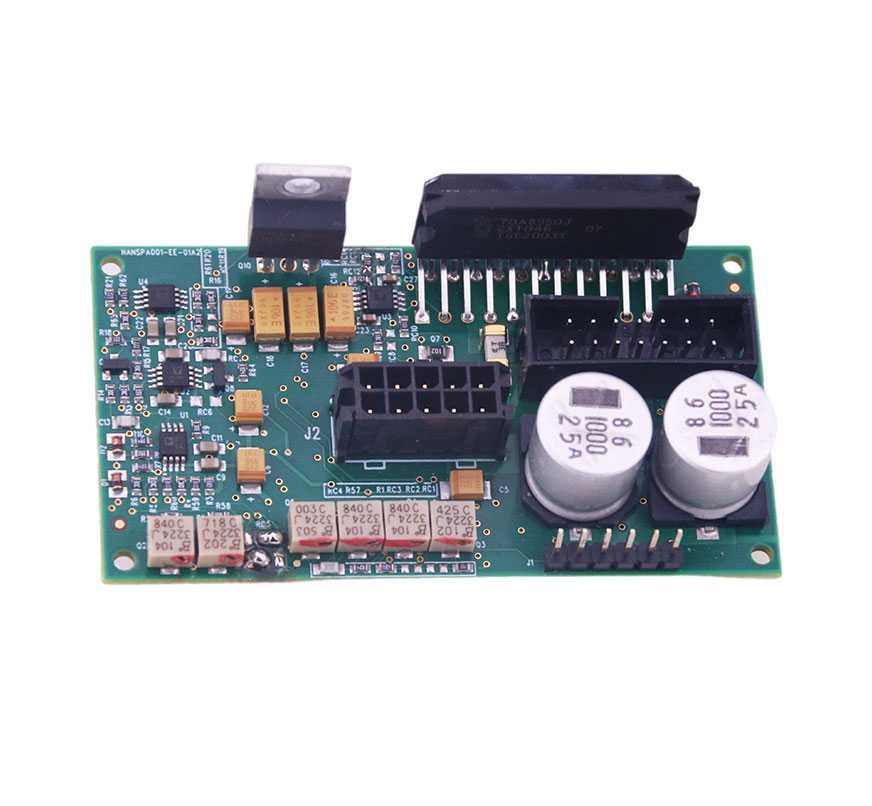
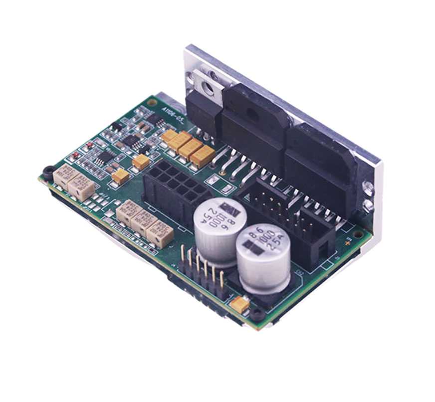
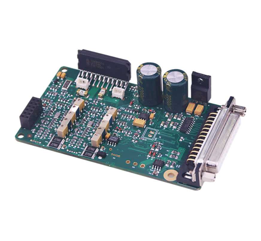
Analog Galvo Driver
€15,000.00
https://www.scanneroptics.com/products/analog-galvo-driver/ ↗
#galvanometer #suppliers
Galvo Definition
Han's Scanner analog galvo driver board is designed for the full series of Han's Scanner photoelectric galvo motor, using the traditional PID closed-loop control mode, stable and reliable performance; with a variety of different configurations, support analog and digital signal input, a variety of different power amplifier devices can drive mirrors with different loads from 3mm-50mm to achieve optimal dynamic performance, to meet the speed and accuracy requirements of various high-end applications.
Key Features Of Analog Galvo Driver
3-in-1 analog driver board
Integrate DA card and analog driver board, compact size
TDA8950 D class work output, low heat
First generation galvo driver
More than 10 years in the market, stable performance
A driver board drives a galvanometer
LM3886 AB dual-power amplifier, maximum 68W+68W power output, strong driving capability
Second generation analog driver board
TDA8950 type D power amplifier output, low heat
A driver board drives a galvanometer, driving capacity is strong
TDA8950 power amplifier, maximum 150W+150W power output, strong driving ability
Improved speed performance by more than 50% compared to the first generation analog driver board.
Specifications Of Analog Galvo Driver
Analog Galvo Driver Electric Parameter
Power Supply Requirements +/-15 to +/-28 VDC Configurations Available
Maximum Drive Current Limit 10 AMPS Peak
5 AMPS Rms (Power Supply And Load Dependent)
Operating Temperature Range 0~50℃
Connector Definition
Description J2 (10pin) Of Driver ST16xx
GND 1
GND 2
GND 3
GND 4
POS1 5
MOTOR+ 6
MOTOR- 7
GND 8
LED+ 9
POS2 10
Description J1 (2pin) Of Driver ST16xx
- 1
+ 2
Description J3 (4pin) Of Driver ST16xx
-15V 3
GND 2
+15V 4
NC 1
Description J4 (10pin) Of Driver ST16xx
NC 1
POS_FB 2
GND 3
CMD_ERR 4
V_CRT 5
V_LED 6
NC 7
NC 8
1. Electronic Parameters
Power Supply Requirements +/-15 to +/-28 VDC Configurations Available
Maximum Drive Current Limit 10 AMPS Peak
5 AMPS Rms (Power Supply And Load Dependent)
Operating Temperature Range 0~50℃
2. lnterface Definitions
Connector Definition
Description J2 (10pin) Of Driver Board ST16XX Remark
GND 1 Power Ground
GND 2 Power Ground
GND 3 Power Ground
GND 4 Power Ground
POS1 5 Photocell Position Feedback Signal 1
MOTOR+ 6 Motor Signal +
MOTOR- 7 Motor Signal -
GND 8 Power Ground
LED+ 9 LED Positive Terminal
POS2 10 Photocell Position Feedback Signal 2
J1 Analog signal control port, communication through serial port
Description J1 (2pin) Of Driver Board ST16XX Remark
- 1 Analog Negative Signal Input (Pulse Signal)
+ 2 Analog Positive Signal Input (Pulse Signal)
Description J3 (4pin) Of Driver ST16xx Remark
-15V 3 Negative Of Power Supply (Current 3A)
GND 2 Power Ground
+15V 4 Power Supply Positive Electrode (Current 3A)
NC 1 Suspend In Midair
Description J4 (10pin) Of Driver Board ST16XX Remark
NC 1 Suspend In Midair
POS_FB 2 Motor Position Feedback Signal
GND 3 Power Ground
CMD_ERR 4 Command Error
V_CRT 5 Motor Current Sampling Signal
V_LED 6 Motor LED Voltage
NC 7 Suspend In Midair
NC 8 Suspend In Midair
As one of galvanometer suppliers, we will do our best to meet all the needs of customers.
#galvanometer #suppliers
Galvo Definition
Han's Scanner analog galvo driver board is designed for the full series of Han's Scanner photoelectric galvo motor, using the traditional PID closed-loop control mode, stable and reliable performance; with a variety of different configurations, support analog and digital signal input, a variety of different power amplifier devices can drive mirrors with different loads from 3mm-50mm to achieve optimal dynamic performance, to meet the speed and accuracy requirements of various high-end applications.
Key Features Of Analog Galvo Driver
3-in-1 analog driver board
Integrate DA card and analog driver board, compact size
TDA8950 D class work output, low heat
First generation galvo driver
More than 10 years in the market, stable performance
A driver board drives a galvanometer
LM3886 AB dual-power amplifier, maximum 68W+68W power output, strong driving capability
Second generation analog driver board
TDA8950 type D power amplifier output, low heat
A driver board drives a galvanometer, driving capacity is strong
TDA8950 power amplifier, maximum 150W+150W power output, strong driving ability
Improved speed performance by more than 50% compared to the first generation analog driver board.
Specifications Of Analog Galvo Driver
Analog Galvo Driver Electric Parameter
Power Supply Requirements +/-15 to +/-28 VDC Configurations Available
Maximum Drive Current Limit 10 AMPS Peak
5 AMPS Rms (Power Supply And Load Dependent)
Operating Temperature Range 0~50℃
Connector Definition
Description J2 (10pin) Of Driver ST16xx
GND 1
GND 2
GND 3
GND 4
POS1 5
MOTOR+ 6
MOTOR- 7
GND 8
LED+ 9
POS2 10
Description J1 (2pin) Of Driver ST16xx
- 1
+ 2
Description J3 (4pin) Of Driver ST16xx
-15V 3
GND 2
+15V 4
NC 1
Description J4 (10pin) Of Driver ST16xx
NC 1
POS_FB 2
GND 3
CMD_ERR 4
V_CRT 5
V_LED 6
NC 7
NC 8
1. Electronic Parameters
Power Supply Requirements +/-15 to +/-28 VDC Configurations Available
Maximum Drive Current Limit 10 AMPS Peak
5 AMPS Rms (Power Supply And Load Dependent)
Operating Temperature Range 0~50℃
2. lnterface Definitions
Connector Definition
Description J2 (10pin) Of Driver Board ST16XX Remark
GND 1 Power Ground
GND 2 Power Ground
GND 3 Power Ground
GND 4 Power Ground
POS1 5 Photocell Position Feedback Signal 1
MOTOR+ 6 Motor Signal +
MOTOR- 7 Motor Signal -
GND 8 Power Ground
LED+ 9 LED Positive Terminal
POS2 10 Photocell Position Feedback Signal 2
J1 Analog signal control port, communication through serial port
Description J1 (2pin) Of Driver Board ST16XX Remark
- 1 Analog Negative Signal Input (Pulse Signal)
+ 2 Analog Positive Signal Input (Pulse Signal)
Description J3 (4pin) Of Driver ST16xx Remark
-15V 3 Negative Of Power Supply (Current 3A)
GND 2 Power Ground
+15V 4 Power Supply Positive Electrode (Current 3A)
NC 1 Suspend In Midair
Description J4 (10pin) Of Driver Board ST16XX Remark
NC 1 Suspend In Midair
POS_FB 2 Motor Position Feedback Signal
GND 3 Power Ground
CMD_ERR 4 Command Error
V_CRT 5 Motor Current Sampling Signal
V_LED 6 Motor LED Voltage
NC 7 Suspend In Midair
NC 8 Suspend In Midair
As one of galvanometer suppliers, we will do our best to meet all the needs of customers.
You might also like

Slim Down with Every Sip: The Fitspresso Coffee Loophole
star
star
star
star
star
4.0/5
$0.00

Discount London theatre tickets
star
star
star
star
star
4.0/5
$22.00

Professional Dissertation Writers India | Mythsis
star
star
star
star
star
4.0/5
$0.00

Buy YouTube Views
star
star
star
star
star
4.0/5
$30.00